6 Simulations and real-world experiments
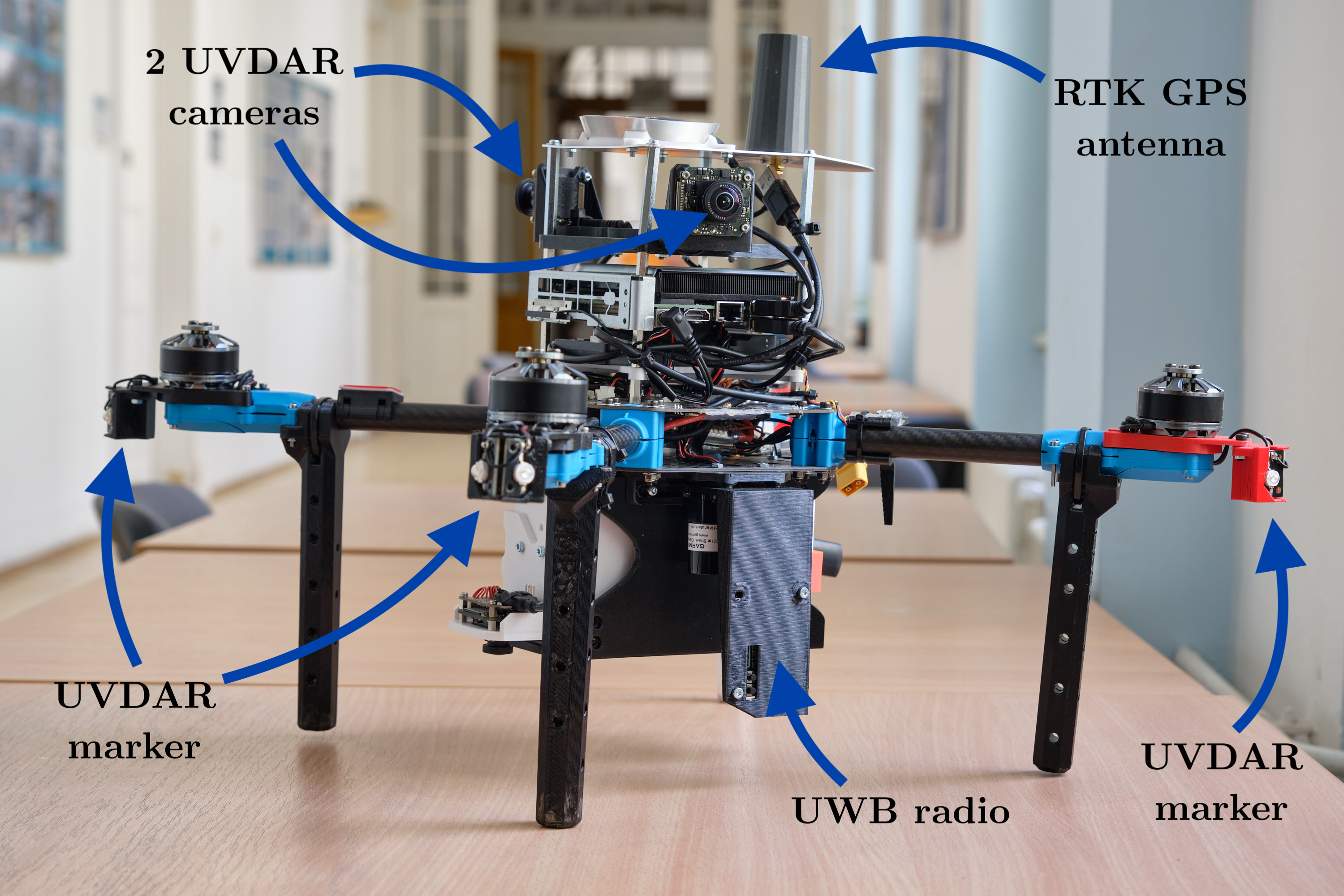
A series of experiments have been conducted to evaluate the performance of the proposed measurement system. Experiments took place at Temešvár (N49.36225 E14.26143). A two Holybro X500 6.1 equipped with Qorvo DWM1000 has been chosen as a UAV platform. These drones were mainly chosen due to the RTK GNSS system onboard, which is crucial for evaluating accuracy by using them as a source of ground truth.
6.1 Ultra-wide band experiments
Line segment test
This experiment aims to test the maximum range and obtain a transfer characteristic of the sensor. The purpose of the first UAV was to act as an observer and, for the duration of the test remained at position \(\begin{bmatrix}0 & 0 & 5\end{bmatrix}^T\). The econd UAV was flying on a trajectory predefined by the parametric equation 6.1.
\[ \mathbf{position}(t) = \begin{bmatrix} 0 \\ 65 + 55 \sin (2 \pi t) \\ 5 \end{bmatrix}, \quad t \in \left(0, 1\right) \tag{6.1}\]
Circular trajectory
As noted above, the results from the UWB should be the same for all orientations. To test whether that is a correct assumption, 4 experiments have been conducted. In each test, one UAV acted as an observer and stayed at position \(\begin{bmatrix}0 & 0 & 5\end{bmatrix}^T\). The second UAV followed a circle of radius 10 m around the first UAV in a car-like motion. The difference between the 4 experiments was the relative angle \(\theta\) as shown in figure 6.2.

Results
All proposed experiments regarding the UWB were successfully conducted. Results from the first experiment in Figure 6.3 showed that the UWB measurements are indeed precise and do not express any signs of nonlinearity. The maximum range of 120 m was reached by UWB, however, the measurements at the far end are not reliable and often drop out.
As Figure 6.5 shows, the measurement error is dependent on the angle. In A sources of error in DW1000 [1] the manufacturer mentions that there are two sources of error, clock drift and received signal level. The implemented ranging technique (double-sided two-way ranging) compensates for clock drift. Therefore, the only error source left is the received signal level. The more powerful the signal, the sooner it is timestamped, leading to a shorter distance reported. This error could be easily corrected by constructing correction function \(f(\mathrm{dB})\). Unfortunately, the received signal level was not recorded. Further research should be done to correct errors dependent on the level of the received signal.
Results and ranging multiple static responders with UWB is demonstrated in Appendix C.
6.2 UVDAR and UWB fusion experiments
Leader follower algorithm
To test the fusion of UVDAR and UWB in loop, a leader-follower algorithm was used. In this test, a leader UAV flies a pre-planned trajectory. A follower UAV tries to follow the leader based only on UVDAR and UWB sensor fusion. The algorithm was inspired by the UVDAR System for Visual Relative Localization With Application to Leader–Follower Formations of Multirotor UAVs [2] and is represented in figure 6.6. The follower was set to follow the leader with \(r = 6 \; \mathrm{m}\) and \(\varphi =\) 180°.

Results
Unfortunately, due to an incorrect configuration of the experiment, the test has not been successfully conducted in real-life. A simulated test using the Gazebo simulator1 was conducted as an alternative approach. A special node was made to simulate results from UWB, the node calculates a distance between UAVs from ground truth and then adds noise with distribution \(\mathcal{N}(0, 0.05)\). The test was repeated two times. First, the UWB and UVDAR fusion was kept for the whole time, providing an accurate position of the leader UAV. During the second test, the fusion process was halted mid-way and only UVDAR measurements were utilized.
The results depicted in Figure 6.7 demonstrate the advantages of fusing the UWB and UVDAR technologies. Due to the absence of precise distance measurements from UWB (Ultra-Wideband) technology, the follower UAV could not maintain track of the leader UAV.
More simulated tests of the Object tracker can be seen in Appendix C.
Gazebo simulator https://gazebosim.org/home↩︎


No matching items